Change Global Sheet Metal Thickness Solidworks

Solidworks 2019 Link Sheet Metal Parameters To Specific Material Youtube
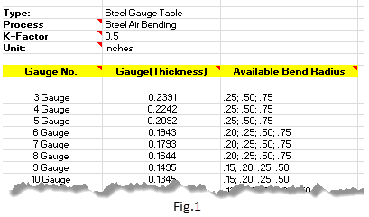
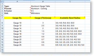
What Sheet Metal Gauge Tables Does Solidworks Provide With Its Installation

Spotlight On Features Sheet Metal And Gauge Table Rules Part I
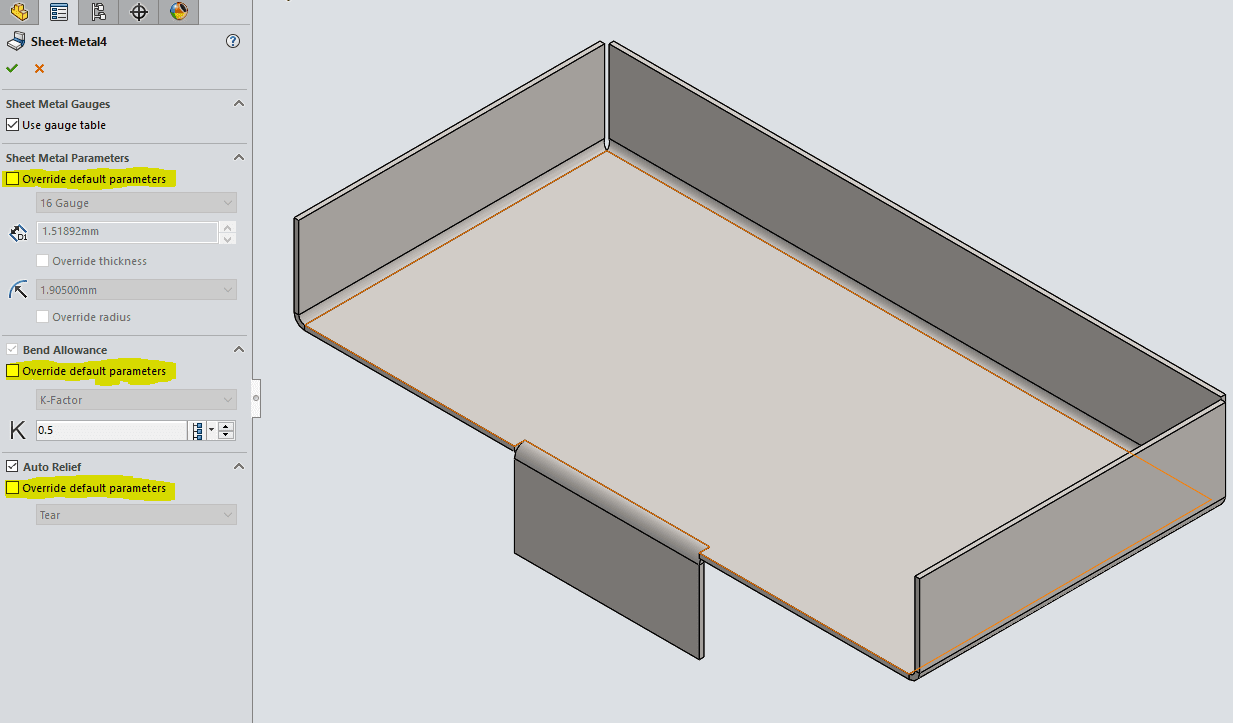
Solidworks 2017 Sheet Metal Options
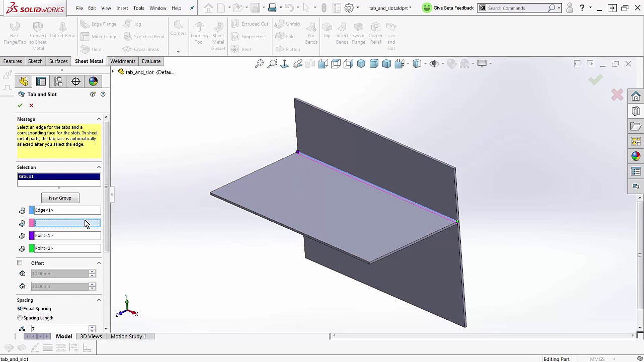
Solidworks 2018 Sheetmetal Tab And Slot Youtube
How To Drive Sheet Metal Parts Kb12121018 Driveworks Documentation

In the featuremanager.
Change global sheet metal thickness solidworks.

How To Unfold Radius Corners Advanced Sheet Metal Made Easy With Topsolid 7 Sheet Metal Metal Sheet Design Solidworks Tutorial

How To Convert Thickness Into A Solidworks Sheet Metal Gauge Value
Http Files Goengineer Com Docs Support Sheet 20metal 20bodies Pdf

Spotlight On Features Working With Sheet Metal Tables Understanding The Measured Parameters
Source : pinterest.com
